
The tube welding unit is the core equipment of the welded pipe production line, and its normal operation plays a crucial role in improving production efficiency, increasing economic returns, and ensuring product quality. Therefore, proper adjustment of the welding unit, along with accurate fault diagnosis and timely troubleshooting, is especially important. Below, we will focus our discussion on the following aspects.

Adjustment of High-Frequency ERW Tube Mill
The "adjustment" we refer to here means the commissioning work performed during the installation of the mandrel. As long as the pipe billet can run smoothly and stably within the unit and produce qualified products, the adjustment task can be considered complete. Any subsequent adjustments made during production should be categorized under fault troubleshooting. Regarding the adjustment of the tube welding unit, it should be carried out in the following steps:
1. Preparation Work
Preparation primarily involves inspecting the quality of the rolls and checking the condition of the equipment. When inspecting roll quality, emphasis should be placed on the shape of the pass (roll groove). During inspection, use pass templates to verify whether each roll's pass conforms to design specifications; if not, the roll must be rejected and cannot be installed. Additionally, special attention must be paid to the bottom diameter dimensions of the rolls, as this is a critical parameter ensuring proper matching between rolls during synchronized operation. For paired rolls, ensure that their dimensions are identical and their shapes match exactly.
When inspecting equipment condition, the following principles can be summarized in a few key points:
- Horizontal shafts must be level; vertical shafts must be straight.
- Roll positioning must be stable without shifting; sliding components must move freely without wobbling.
- Adjustments should feel smooth and effortless.
- Fixed components must be securely fastened; moving components must operate smoothly - no "stuck adjustments," "wobbling when moved," or "back-and-forth drifting" should occur.
Any component failing to meet these requirements must undergo maintenance or repair to restore its basic functional performance.
2. Alignment (Centering)
Pass alignment is the first step in the adjustment process. During alignment, a 0.5 mm diameter steel wire can be selected, using the distance from the forming mill's entry roll to the sizing mill's calibration roll as the reference length. After determining the centerline of the rolling line, secure the steel wire tightly. The height of the steel wire should be positioned slightly more than 2 mm above the bottom diameter of the horizontal rolls (Figure 1). This prevents the steel wire from contacting the curved surfaces of the pass grooves, which could interfere with the accuracy of the alignment. This steel wire serves as the central reference line for pass alignment.

3. Horizontal Roll Alignment
There are two methods for aligning horizontal rolls:
The first method involves using fixed shims of different thicknesses, selected according to the varying thicknesses of each pass groove (Figure 2). However, this method can easily introduce cumulative errors during assembly if component machining precision does not meet requirements, directly affecting the effectiveness of pass alignment.
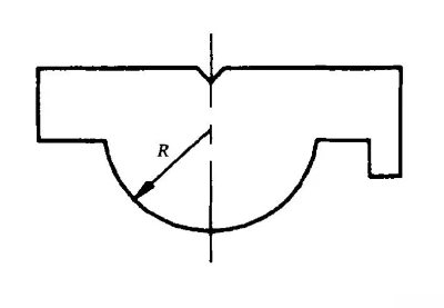
The second method uses locknuts to adjust the axial position of the rolls on the shaft (Figure 3), ensuring that the center of each pass groove aligns with the central reference line. The positioning of the pass center is verified using a dedicated template (Figure 4). During inspection, insert the template into the pass being aligned and slowly lift its upper end. If the steel wire smoothly drops into the center slot of the template, this indicates that the pass center is correctly positioned; otherwise, axial adjustment is required. This is a relatively simple and effective alignment method.


The alignment of the upper horizontal roll is based on the lower horizontal roll. First, calculate the center distance between the upper and lower horizontal rolls, then adjust the upper roll to a horizontal position.
After leveling the upper roll, the axial center position of the upper roll in an open pass can also be located using a template-style gauge to check whether the side clearances between the lower and upper roll passes are identical (Figure 5). If they match, the axial position of the upper roll can be locked. For closed passes, the "touch method" can be used to verify whether the upper and lower passes align properly.

4. Vertical Roll Alignment
Vertical roll alignment can be carried out in three steps:
First, determine the opening gap for each pair of vertical rolls - that is, the center-to-center distance between the two vertical rolls.
Second, locate the center position for each pair of vertical rolls.
Finally, adjust the height of the vertical rolls.
The opening gap of the vertical rolls should be based on the designed deformation opening width of the pass, then reduced by approximately 5 mm (Figure 6).

If the reduction is too large, it will accelerate wear on the upper edge of the vertical roll pass and simultaneously increase equipment load. The center alignment of the vertical rolls should be performed simultaneously with that of the horizontal rolls to ensure that the centers of both horizontal and vertical rolls lie on the same centerline. Once the centerline of the vertical roll pass has been aligned, lower the steel wire onto the bottom diameter position of the horizontal roll pass to begin adjusting the height of the vertical rolls. The height of the vertical rolls should be adjusted so that the lower edge of the vertical roll pass aligns with the height of the steel wire (Figure 7).

The height of the vertical rolls in the initial forming stands should be determined according to the process parameters for the amount of material removed from the lower roll ring (the hatched areas in the diagram indicate the portions of the roll ring that are machined away).
5. Alignment of Other Passes
The alignment methods for other passes can follow the principles used for horizontal and vertical rolls. However, the bottom diameter position of the guide roll should be set slightly higher than the reference line by 0.5 to 2 mm (depending on the pipe diameter and wall thickness being produced). The burr support roll should be positioned 0.5 mm above the reference line to ensure more stable force distribution during external burr removal and prevent chattering during the trimming process.


